Industrial Hydronic System Manual-Balancing Methods
By Brandon Aitken, ME, P.E., Engineering & Fabrication Manager, Blackhawk Equipment Corporation
07/25/2016
Hydronic balancing in industrial heating and cooling systems is an often overlooked final step in startup and commissioning of new and modified hydronic systems. Insisting on a complete system balance upon startup of a new or modified system is an inexpensive insurance policy for any design engineer or installation contractor to protect their reputation against a system that is not performing to design conditions. There are several methods of hydronic system balancing utilized in commercial and hospitality buildings, however, they are rarely found in the manufacturing and industrial environments.
Manual-Balance Using Calibrated Balancing Valves and Reverse-Return Piping
The most common of the various methods of system balance, found in industrial and manufacturing facilities, is manual-balance using calibrated balancing valves and reverse-return piping. Manual- balance utilizes calibrated balancing valves to restrict and meter flow to a coil. A calibrated balancing valve is an adjustable orifice flow metering device. The valve manufacturer develops flow characteristics of the valve by creating a flow/pressure relationship allowing flow to be accurately measured and controlled via pressure drop across the valve. The flow rate can be infinitely adjusted and set via graduated markings, or set points on the valve body.
Reverse-return systems, where the first process equipment supplied cooling water is the last equipment to be returned, are elegant and a simple means of balancing cooling water systems. However, they are implemented less often in manufacturing and industrial systems due to their added upfront costs of additional pipe and they are not always practical if heat loads are scattered in a non-uniform pattern around the facility. This article focuses on the ill effects of a hydronic system that is out of balance and the corrective steps to balancing a system using manual-balance method.
Case Study
Blackhawk Equipment Corp. recently completed a study at a manufacturing facility experiencing severe problems with their cooling process and support equipment. These issues had become so significant they were negatively effecting production resulting in increased scrap rates and intermittent shutdowns of production.
The facility had recently undergone a major project where a new manufacturing line was installed. The project design engineers had determined the existing cooling tower was adequate to reject the additional heat load the new production equipment would produce but the system pumps and main header were upsized to accommodate additional flow. Shortly after the new manufacturing line was brought online, problems cooling the new and existing equipment began.
In an effort to increase cooling to the production equipment, additional heat exchangers were added to the production equipment and pump and cooling tower efficiencies were investigated and adjusted. These actions resulted in minimal improvements cooling the production equipment. The plant management was ready to replace their entire cooling water system when Blackhawk Equipment was solicited to analyze the cooling water system and provide observations and corrective actions.
Blackhawk’s Observations
-
There was a lack of balancing valves present in the distribution piping. Balancing valves were not installed at the process equipment heat exchangers nor in the main branch piping.
-
Return water pressure varied greatly between production lines (3psi – 5 psi on the legacy production lines, and 24psi on the new production line).
-
The average cooling water flow varied drastically between manufacturing lines. (see figure #1).
-
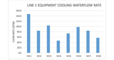
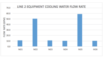
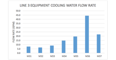
Flow between identical pieces of production equipment varied significantly (See figures #2, #3, & #4).
 Figure 1: The average cooling water flow varied drastically between manufacturing lines.
Imbalanced Cooling Water Distribution Piping
It was concluded the cooling water distribution piping was in a state of severe imbalance. The pipe installed during the installation of the new manufacturing line was found to be short cycling the cooling water system, reducing the flow to the legacy manufacturing lines. In addition, the distribution pumps were operating on the far right part of their flow curves producing more flow but less pressure then how they were designed to operate, another negative effect of an out of balance system. The unrestricted flow of cooling water to the new production line wasn’t allowing the system distribution pumps to build enough pressure to adequately circulate water to the legacy production equipment which were located ~200+ feet further away from the cooling water pumps than the new line.
Blackhawk Equipment recommended the installation of over 30 calibrated balancing valves from ¾” to 3” to be installed on the return water side of all production and support equipment that required cooling water. Once installed Blackhawk spent several days observing and balancing the system. After which the system flow was being evenly distributed between production lines and individual pieces of equipment. The overall pumping power was reduced, scrap rates were decreased and stops in production from overheating equipment were eliminated.


Figure 2-4: Flow between identical pieces of production equipment varied significantly.
A 5-Step Process to Use Manual–Calibrated Balance Valves
If utilizing a test and balance firm is not in the budget a few simple steps during the startup and commissioning of a new or modified hydronic system can provide a rough system balance to help insure the new system will perform up to design conditions and end user expectations. The procedure for balancing using manual calibrated balance valves can be boiled down to a simple 5 step process:
-
Open all balance valves 100%, verify all air has been evacuated from the system, and verify heat exchangers are properly plumbed.
-
This will help establish the pre-balance pump operating point and system flow rate.
-
(There are many good choices of valves on the market but my calibrated balancing valve of choice is the Bell & Gossett Circuit Setter, this is a robustly built valve equipped with upstream and downstream pressure ports and the SystemSyzer phone application works well for setting up flow through the valve quickly).
-
Moving away from the pumps increase the percentage of full flow equally for each coil from the first to the end of piping then return to the first coil and check the flow.
-
The system pressure should have risen and the flow should be reduced from the starting point.
Conclusion
When trouble-shooting over-heating equipment, hydronic system balancing should always be considered during the root cause analysis. Often times fouled heat exchangers or failing cooling water equipment are misdiagnosed and the underpinning cause is actually a system balance issue. Hydronic system balancing should be completed on new systems and any time a significant system modification takes place.
Side note: Balance valves and flow control valves should always be installed on the return side of heat exchangers. This keeps the pressure in the heat exchanger higher, preventing air entrained in the cooling water from coming out of solution and building up in the heat exchanger.
For more information please contact Brandon Aitken P.E., Engineering & Fabrication Manager, Blackhawk Equipment Corporation, tel: 303.421.3000, email: , www.blackhawkequipment.com.
To read similar Cooling System Assessment articles, please visit www.coolingbestpractices.com/system-assessments.
